Powered by Blogger.
RSS

ITD ::: All you need to know about IP address

All you need to know about IP address

What is IP address?

If you aren't sure what IP address is, IP (Internet Protocol) address is a unique address that identifies a computer or a device on the Internet. It contains 32 bits or 4 bytes (octets) and is written in four sets of decimal numbers separated by a period (or dot) in between. Each set of decimal numbers represents a byte (i.e. 8 bits) and can not exceed 255, that is when all the eight bits are 1 (or 11111111). Example of IP address: 202.60.80.1
An IP address is comparable to a telephone number that uniquely identifies an individual or a business on the telephone network.

==>> The anatomy of IP address

Every computer or device on the Internet is part of a network (e.g. ISP, corporate, or home network). That's why IP address body (i.e. xxx.xxx.xxx.xxx where x is a decimal number) consists of network identity (ID) and host (i.e. node/device) ID. A subnet mask value which resembles an IP address is usually given along with an IP address to help identify which part of the address refers to network ID or host ID. Subnet is logical grouping of hosts in a network that functions to segregate traffic.
In a class A IP address, the first byte refers to network ID and the last three bytes refer to host ID. In a class B IP address, the first two bytes refer to network ID and the last two bytes refer to host ID. In class C IP address, the first three bytes refer to network ID and the last byte refers to host ID. Class A IP addresses are used by very big networks, class B by medium to large networks, while class C by small networks.
  From To Default subnet mask
Class A 0.0.0.0 127.255.255.255 255.0.0.0
Class B 128.0.0.0 191.255.255.255 255.255.0.0
Class C 192.0.0.0 223.255.255.255 255.255.255.0
 Example, if your computer IP address is 192.168.1.3 (a class C IP address), it must belong to a network (LAN) with this network address 192.168.1.0 and its host ID is 3.


What is my IP address?

Your IP address currently is 119.73.71.173
When your computer (be it a desktop PC, laptop/notebook, netbook, tablet, handheld/PDA, or smart phone) accesses the Internet, it has an IP address that is assigned to it by your ISP or a broadband router in your home or company network. IP address is different with MAC address. A MAC address or physical address was assigned to a device by its manufacturer and stays the same during its lifetime while IP address depends on the network or service provider through which your computer or device gets an Internet connection.
For example, if you use Windows XP, to check your IP address, do one of the following:
1) double-click your Internet connection icon on the taskbar and click the Details tab.
2) open the Command Prompt window and type this command : ipconfig or ipconfig /all. You can go to the Command Prompt through Start > All Programs > Accessories > Command Prompt. [To find Command Prompt in Windows Vista or Windows 7, just click Start button and type cmd in the search box and press Enter.]
3) go to Network Connections folder, click on your Internet connection name, and see your IP address on the Details pane on the bottom left of the folder. You can go to the Network Connections folder through Start > Connect To > Show all connections or through Control Panel. [In Windows Vista or Windows 7, right click a connection icon on the taskbar/system tray, select Network and Sharing Center. On the left pane, select Manage network connections to open Network Connections folder. Right click an active connection, select Status, and click Details.]

Dynamic IP address vs. static IP address

When your computer connects to your ISP, your ISP assigns an IP address to it. In the case of dial-up access over telephone line or broadband access (e.g. DSL or cable modem) using PPPoE/PPPoA that requires log-in, your computer will get a different IP address each time it connects to the ISP and makes an Internet connection through it. This address is called dynamic IP address. The IP address is assigned by a DHCP server at your ISP. This this the most common case since every ISP has limited IP addresses stock. On the other hand, using an always-on broadband connection, your computer is usually given the same IP address all the time by the ISP. This address is called static IP address.
Dynamic IP address is assigned to your computer by a broadband router (or residential gateway) if your computer is on a LAN (home or office network) and accesses the Internet through a broadband router. But this address is for internal use only, it gets converted to a public IP address when communicating over the Internet. Dynamic IP address assignment is handled by a DHCP server at the router. The DHCP server can be set to reserve an IP address for a computer during a connection or change it periodically at a predefined interval. The router also handles the network address translation (NAT), i.e. converting private IP address assigned by the DHCP to a public IP address assigned by the ISP.


Private IP address vs. public IP address

Private IP address is only used within a LAN or an internal network (e.g. home or company network), while public IP address is used for communication over the Internet. If your computer is part of a company network, chances are it is assigned a private IP address and when it connects to the Internet the private IP address is translated to a public IP address by a router which has NAT capability. Private IP address is also known as internal IP address, while public IP address is external IP address. LAN IP address is always a private IP address, while WAN IP address can be a private or public IP address. This article clarifies the difference between LAN IP address and WAN IP address.
OK, in case you are wondering, the table below tells you which IP addresses are allocated for use only in internal networks as private IP addresses.
IP address class private IP address range
  From To
Class A 10.0.0.0 10.255.255.255
Class B 172.16.0.0 172.31.255.255
Class C 192.168.0.0 192.168.255.255


What is the function of IP address?

IP addresses are used by devices called routers on the Internet to forward messages from one computer to another over the Internet. In comparison to a telephone network, a router acts like a telephone switch (exchange) that connects a caller to the dialed phone number.
When you send a message over the Internet, the message is broken down into small pieces - called packets - where each packet can take its own route. IP addresses information is included in the packet header. Your computer sends each packet along with your computer (i.e. source) IP address and the receiving computer (i.e. destination) IP address. The routers read the source and the destination IP addresses by examining a packet header and forward the packet accordingly.
However, you usually type a web address (e.g. www.conniq.com) instead of an IP address in your browser's address bar. That's because there are servers on the Internet that store the mapping of web addresses to IP addresses. They are called DNS servers. The DNS servers handle the translation from a web address to an IP address. A DNS server is analogous to a telephone directory that contains a list of telephone numbers and businesses or individuals who own the numbers.


==>> How many routers do forward my message before arriving at a specific web address?

Your message does not get to the destination address via one router. There are many routers involved in forwarding your message to the destination computer (i.e. in this case, a web server). You can do little investigation by typing tracert ip_address or tracert web_address in Command Prompt. Replace the ip_address or web_address part after tracert with your destination, e.g. www.myexampledestination.com. This command will trace the routes that take your message to its destination by sending ICMP messages. Some routers have been set not to accept an ICMP message from the Internet therefore you won't get a reply. But since many allow it, by reading the result you would be amazed at how far your message can travel in milliseconds and how many hops it makes to get to its destination.


How will the website I visit use my IP address?

Your IP address can be used for location targeting that is identifying where you come from and presenting you relevant content tied to your geographic location. That's because IP addresses in bulk are allocated to regions and countries around the world by the IANA in a delegated manner through several Regional Internet Registries. And each ISP obtains IP addresses for its subscribers from Local or National Internet Registry.
Nonetheless, a website you visit can not know who you are, solely from your IP address. Unless you register to the website and gives it your personal information, you will remain anonymous.


 

  • Digg
  • Del.icio.us
  • StumbleUpon
  • Reddit
  • RSS

ITD ::: WiMAX in a Wi-Fi Mesh Network

WiMAX in a Wi-Fi Mesh Network

Mesh topology is not supported by existing IEEE's wireless LAN standards but it becomes popular as city-wide (municipal) Wi-Fi network deployment gains more supporters day after day. In a mesh network, each node (i.e. base station or access point) connects to several neighboring nodes and on to a mesh gateway (i.e. a base station that aggregates the mesh network traffic and routes it to the Internet). Since each node has many routes to a mesh gateway, mesh network is very reliable. But mesh network is more complex to manage and poses interference challenge especially for operation in a license-exempt band such as in Wi-Fi case.
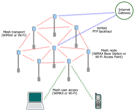
WiMAX access, transport, and backhaul in a municipal Wi-Fi mesh network
Figure. Mesh Network with Wi-Fi and/or WiMAX
WiMAX can work on all layers of a municipal mesh network (hotzone/metro zone).
By examining current Wi-Fi mesh network architecture, basically there are three layers. These are mesh access handling user access to a mesh node, mesh transport interconnecting mesh nodes and routing traffic to mesh gateways, and backhaul connecting a mesh gateway to an Internet PoP (Point of Presence) or other content gateways.
Backhauls for mesh Wi-Fi networks are provided using various wired and wireless solutions, i.e. fiber optic, leased line, DSL, and proprietary point-to-point (PTP) or point-to-multipoint (PMP) radio including some pre-WiMAX equipment. A wireless backhaul - specifically WiMAX - enables flexible placement of a mesh gateway node anywhere in the network, therefore it doesn't have to be located in a telco's CO or close to a fiber/DSL termination point. The portable WiMAX equipment (Base Station) also allows fast installation and easy relocation. Moreover, WiMAX was designed for outstanding performance in NLOS environment, typical in metro area with many high rise buildings. WiMAX also can operate either on licensed or unlicensed band, giving more options for operator/ISP/municipality in addressing various interference conditions and users' requirements.
The mesh transport layer provides the interconnection between mesh nodes. There is a project in the IEEE to standardize Wi-Fi as an intra-mesh transport solution, but the work is still in progress. The current established Wi-Fi solution uses proprietary technology developed by each vendor which might cause interoperability issues in the future. WiMAX can naturally replace Wi-Fi in this layer, interconnecting mesh nodes using standard equipment based on the IEEE 802.16-2004 or 802.16e which includes support for optional mesh topology. Besides, WiMAX has built-in QoS support and is optimized for longer distance (WiMAX is a wireless MAN while Wi-Fi is a wireless LAN) .
For mesh access layer, at present users connect using their Wi-Fi-enabled laptops, PDAs, or smart phones. WiMAX integration into such portable/mobile devices is still in its early stage of development. However, in several months/years to come one may expect the emergence of dual-mode Wi-Fi/WiMAX devices and network adapters (NIC, PC card, PCI Express) which can connect automatically to any available network with the best signal.

  • Digg
  • Del.icio.us
  • StumbleUpon
  • Reddit
  • RSS

ITD ::: Fiber Optic Multiplexer -Mux 8 To 16 Port VDC And VAC

Fiber Optic Multiplexer 8 or 16 ports
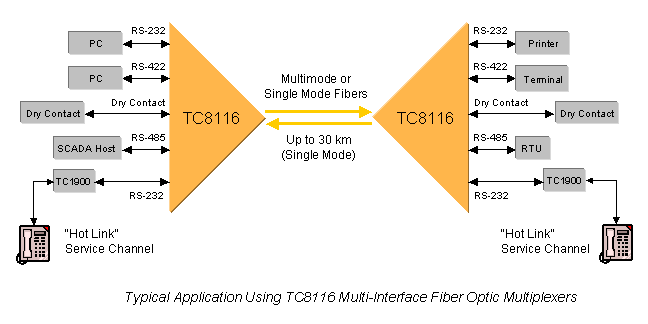
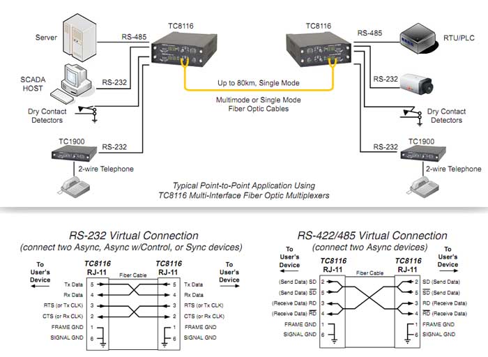
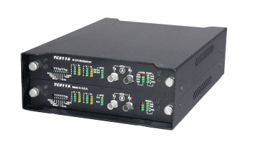
The TC8116 is an 8 or 16-channel fiber optic multiplexer with interchangeable interfaces and built-in power redundancy. Standard interfaces include RS-232, RS-422, TTL, RS-485 & Dry Contact Closure.  Electrical interfaces are modular and interchangeable in 4-channel increments at any time--before or after installation.  Because different interfaces can be mixed in 4-Channel increments, a wide variety of interface combinations are available

8/16 Channel Multi-Interface 
(Model TC8116)    Related Products:  TC8108


  • Mix or Match Field-Interchangeable Interfaces: RS-232, RS422, RS-485, TTL, & Dry contact Relays
  • Data Rates up to 56 Kbps*
  • 8 or 16 Channels
  • Built-In Power Redundancy
  • Optional Optical Redundancy
  • Local Dry Contact Relay
  • Built-In Test Signal Generator
  • Local & Remote Loopback Features
  • Multimode or Single Mode (850/1300/1550nm)
  • Rackmount or Standalone
  • Extend telephone lines with TC1900 RS-232/Fiber Phone Extenders
  • Dimensions: Chassis Style SD10
 

Applications

The TC8116 Fiber Optic Multiplexer provides a flexible, inexpensive method for connecting async/sync terminals, printers, and status collecting devices.  It is often used in harsh environments where EMI/RFI interference, ground loops and lightning conditions may exist.  The TC8116 can also be used to extend telephone lines to remote locations with the Model TC1900 RS-232/Fiber Phone Extenders.

Description

The TC8116 is an 8 or 16-channel fiber optic multiplexer with interchangeable interfaces and built-in power redundancy. Optical redundancy is optional. It supports data rates up to 56Kbps*. The TC8116 is available in four configurations:
  • 8 Channel Async Multiplexer
  • 8 Channel Sync/Async Multiplexer
  • 16 Channel Async Multiplexer
  • 16 Channel Sync/Async Multiplexer


Standard interfaces include RS-232, RS-422, TTL, RS-485 & Dry Contact Closure.  Synchronous versions must be RS-232.  Electrical interfaces are modular and interchangeable in 4-channel increments at any time--before or after installation.  Because different interfaces can be mixed in 4-Channel increments, a wide variety of interface combinations are available.


Diagnostics are extensive and include DIP switches for Local & Remote Loopback, a Test Signal Generator, an Electrical Signal Polarity Inverter, and other application configuration switches.  Each unit also provides multiple LEDs for Alarm, Power, Vcc, Optic Signal Status, and Tx & Rx LEDs for each channel.  The built-in test signal generator verifies both device and fiber optic link operation.  This feature benefits users by helping technicians verify that both local & remote devices and the fiber optic link are operating normally.  No other test equipment is required for link and device verification.
The TC8116 is compatible with all types and sizes of multimode (850/1300nm) or single mode (1300/1550nm) fiber optic cable.  Fiber optic connectors are ST or FC.  Electrical connectors are RJ-11.  Power is 12VDC (standard) or 24VDC, -48VDC, or 115/230VAC with an external power cube.  An extreme temperature version (-20o to 70oC), Model TC8116T, is also available.

Specifications
Data Rates (per channel)
 
 ....................................to 38.4 Kbps
Channel Capacity
  
Async..................................8 or 16
   Sync (RS-232 only)..............8 or 16
Optical 
   Transmitter....................LED/ELED
   Receiver........................PIN Diode
   Wavelength
    ...........................850/1300nm MM
    .........................1300/1550nm SM
   Fiber Optic Connectors
   ........................... ST, FC Optional
   Loss Budget* -850/1300/1550nm
   Multimode @ 62.5/125µm........15dB
   Single Mode @ 9/125µm.........15dB
 Visual Indicators  System
   
Channel Status (each channel).....
   Tx, Rx, System, Power A, Power B
   VccA VccB, ALARM
   Optic SYNC. RxA, RxB, USE RxA,
   USE RxB, OPTIC, RxB
System
  
Bit Error Rate.........1 in 109 or better
Electrical
   
Connector..................RJ11 Female
   Interface...........(standard)  RS-232,
   ........... RS-422,  Dry Contact Relay
   Interface (custom)  TTL, 2 or 4-wire
   ...............RS-485* or a combination
Alarm

   Dry Contact Normal................OPEN
Power
  
Standard............12VDC @ 400mA
   Optional............................24VDC,
    ............. -48VDC, or 115/230 VAC
    with external power cube
Temperature
  
Operating....................-10° to 50°C
   Hi-Temp (optional)........-20° to 70°C
   Storage ......................-40° to 90°C
   Humidity.........95% non-condensing
Physical (Rackmount Card)
  
Height.........................(3.53cm) 1.4"
   Width.......................(18.10 cm) 7.1"
   Depth.......................(24.80 cm) 9.8"
   Weight.......................(280gm) 8 oz.
*Contact factory for higher requirements (Laser)

  • Digg
  • Del.icio.us
  • StumbleUpon
  • Reddit
  • RSS

ITD ::: BlueTree GSM-GPRS Cell Cellular Modem with GPS

BlueTree GSM-GPRS 
Cell Cellular Modem with GPS
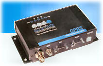
The BT-2010 GSM GPRS cell modem is designed to military (MIL) and automotive (SAE) specifications for ruggedness in harsh environments, including temperature, humidity, vibration and shock. Integrated mounting feet make it suitable for mounting in a vehicle or other harsh environments
  • BT-2010 GPRS Standard GSM Cellular Modem with GPS
  • RUGGED - RELIABLE - HIGH PERFORMANCE

  • Rugged Design
  • Dual-Band GPRS 850Mhz and 1,900Mhz
  • High-Speed Data
  • Maximum Power and Coverage
  • Standard Communications Protocols
  • Modem Management Software - BlueVue
  • Proven Reliable RF Module
  • GPS
The BT-2010 modem is designed to military (MIL) and automotive (SAE) specifications for ruggedness in harsh environments, including temperature, humidity, vibration and shock. Integrated mounting feet make it suitable for mounting in a vehicle or other harsh environments
The BT-20x0 modem supports both North American GPRS frequencies, including 850 MHz and 1,900 Mhz.
The BT-2010 supports GPRS Class 8, meaning it provides the highest  possible throughput available on GPRS networks (up to 56 kbps).
The BT-2010 modem uses a full power transceiver and high-efficiency screw-on antenna connector. Users benefit from optimum signal strength and coverage.
The BT-2010 modem supports: GPRS packet data connections CSD circuit-switched (dial-up) data connections Serial RS-232 (or optional USB adapter)
Communications protocols: AT commands and PPP
BlueVue modem management software provides a Windows™-based graphical interface that allows you to: Program the modem Monitor status of connections Initiate connections/data sessions View diagnostic info, such as signal strength, and network status GPS - display and redirection
The BT-2010 uses the RIM1902G GPRS RF module. The result is the ultimate in reliability from the industry leaders in GPRS technology.
The BT-2010 provides standard GPS. The modem incorporates an internal Trimble Lassen SQ GPS module and supports standard TSIP, TAIP and NMEA 0183 protocols. The GPS information is available on the secondary serial port.
Customers benefit from the support of our Value-Added Resellers and from the knowledge of BlueTree's development team. Our 1-year warranty is included, plus optional 3-year extended warranty for total protection.
BlueTree focuses exclusively on wireless modems for mobile and industrial applications. The BT-series modem provides all the ruggedness you need without additional features you don't.

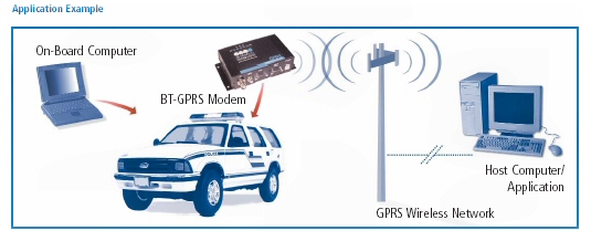
APPLICATION EXAMPLES
  • Police, Fire, EMS and other Emergency Services
  • Public Transit and Transportation
  • Vehicle Tracking - AVL
  • Field Service & Mobile
  • Dispatch
  • Utility Automatic Meter
  • Reading (AMR)
  • Automated machine-to-machine
  • (M2M)
  • Telemetry and SCADA

  • Digg
  • Del.icio.us
  • StumbleUpon
  • Reddit
  • RSS

ITD ::: Flexpoint 100FF 100FX/100TX Single-Mode To Multimode or Multimode To Single-Mode Fiber Coverters

100FX Single-Mode to Multimode
Fiber converter


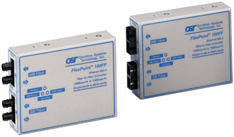
The FlexPoint 100FF Single-Mode to Multimode Fiber Converter supports Ethernet and Fast Ethernet and Token Ring.

Flexpoint 100FF

Single-Mode to Multimode or
Multimode to Single-Mode
Fiber Converters
for 100FX -100TX Fast Ethernet
FlexPoint 100FF
The FlexPoint 100FF Single-Mode to Multimode Fiber Converter supports Ethernet and Fast Ethernet and Token Ring. Capable of extending network distances up to 58 km (36 mi.) over single-mode fiber.
Available with SC and ST connectors in a variety of both multimode and single-mode fiber combinations.
Operates in half duplex or full duplex.
Supports 10Base-FL, 100Base-Fx and IEEE 802.3 specifications.
Wall-mountable or rack-mountable on a 5-unit shelf or in the 14 unit power-redundant FlexPoint Powered Chassis.
Out-of-the-box plug-and-play operation.
Software-independent.
Lifetime warranty.

The FlexPoint 100FF Single-Mode to Multimode Fiber Converter is a member of the modular FlexPoint product line. The FlexPoint product line supports the IEEE 802.3 standard and provides an extensive range of connectivity options across different media types.
The FlexPoint 100FF Single-Mode to Multimode Fiber Converter provides a cost-effective solution to extend network distances by connecting multimode fiber networks or devices over single-mode fiber cabling.
The FlexPoint 100FF provides diagnostic data through LED indicators that assist in network installation and maintenance. The LEDs report the availability of power and the detection of devices attached to the fiber ports.
The FlexPoint 100FF offers several mounting options. It can be mounted stand-alone utilizing optional wall-mounting hardware. It can also be rack-mounted using a 5-unit rack-mounting shelf or be installed in a rack-mountable, high-density, 14-unit, power-redundant chassis.

Specifications
FlexPoint 100 FF 
Connectors and Cables:  
Fiber:
SC or ST
Multimode:
50/125, 62.5/125, 100/140 µm
Single-Mode:
9/125 µm
Supported Distances:  
Ethernet and Token Ring:
 
Multimode:
5 km/16,400 ft.
Single-Mode:
20 km/66,000 ft.
Fast Ethernet:
Half-Duplex Full-Duplex
MM/Sx, 850 nm:
412 m/1,350 ft. 500 m/1,640 ft.
MM/Lx, 1300 nm:
412 m/1,350 ft. 5 km/3.1 mi.
SM/Lx, 1300 nm:
412 m/1,350 ft. 28 km/16.8 mi.
SM/Lx/LH, 1300 nm:
412 m/1,350 ft. 58 km/36 mi.
Indicators:  
Power:
LED, Yellow, power applied
Fiber Link/ Receive:
LED, Green, Link/ data received
Dimensions/Weight: W:3.0"xD:4.0"xH:1.0"/ 6 oz.
Power: 9 VDC/500 mA or 5 VDC/750 mA
Physical/ Environmental:  
Temperature: Operating: 0 to 70 degrees C
  Storage:: -40 to 80 degrees C
Humidity:
0-90% (non-condensing)

Ordering Info
DC power the X will be 0
as in 4411-0
115VAC power the X will be 1
as in 4411-1
220VAC power the X will be 2
as in 4411-2
Model
Port 1
Port 2
Media Type
Distance
Media Type
Distance
4411-x
MM/SC/Lx 1310 nm
5 km
SM/SC/Lx 1310 nm
28 km
4412-x
MM/ST/Lx 1310 nm
5 km
SM/ST/Lx/LH 1310 nm
58 km
4413-x
MM/SC/Lx 1310 nm
5 km
SM/SC/Lx/LH 1310 nm
58 km
4410-x
MM/ST/Lx 1310 nm
5 km
SM/ST/Lx 1310 nm
28 km
4414-x
MM/ST/Sx 850 nm
500 m
SM/ST/Lx 1310 nm
28 km
4415-x
MM/SC/Sx 850 nm
500 m
SM/SC/Lx 1310 nm
28 km
4416-x
MM/ST/Sx 850 nm
500 m
SM/ST/Lx/LH 1310 nm
58 km
4417-x
MM/SC/Sx 850 nm
500 m
SM/SC/Lx/LH 1310 nm
58 km
4418-x
MM/ST/Sx 850 nm
500 m
MM/ST/Lx 1310 nm
5 km
4419-x
MM/SC/Sx 850 nm
500 m
MM/SC/Lx 1310 nm
5 km
4420-x
MM/ST 1310 nm
5 km
MM/ST 1310 nm
5 km
4421-x
MM/SC 1310 nm
5 km
MM/SC 1310 nm
5 km

  • Digg
  • Del.icio.us
  • StumbleUpon
  • Reddit
  • RSS

ITD ::: Gigabit Ethernet Converter/Extender GSM-1000 GSM-1010

Gigabit Ethernet Converter/Extender
GSM-1000 GSM-1010

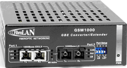
This Gigabit Ethernet Converter by Fibrolan provides conversion from a Multi-Mode (1000Base-SX) or Single Mode (1000Base-LX) Link to a single-mode (1000Base-LX) link allowing its extension of up to 80km. The GSM-1000 and the GSM1000M managed  fiber to fiber converters to the Copper GSM-1400 / GSM-1400M fiber converters.

  • Digital Conversion - stability, feature rich, cascading
  • Network extension - up to 80km
  • Reliability - internal PS (-48VDC PS optional)
  • Versatile installation - desktop, shelf or wall-mount
  • LST and Loop-Back - for enhanced diagnostics
  • SNMP managed versions
  • MA managed versions

    printer friendly PDF
  • http://www.arcelect.com/GSM1000.pdf

This Gigabit converter provides conversion from a Multi-Mode (1000Base-SX) or Single Mode (1000Base-LX) Link to a single-mode (1000Base-LX) link allowing its extension of up to 80km. As many of the GBE switches or NICs come with SX ports, combining such with the GSM1000 provides the most flexible and cost effective way to extend their reach over fiber. The GSM1000 is based on a full digital technology: analog signals from one port are converted to digital electrical signals, fully retimed then converted again to the second F/O port. This design provides a reliable and steady conversion , advanced control/diagnostic features and Management. In addition it allows cascading of several devices, reaching distances of hundreds of km. FibroLAN's unique Link Segmentation Test (LST) allows easy link segmentation (selective per port) to facilitate network diagnostics and overcomes the fault propagation which is inherent to GBE F/O links. A Loop-Back function on each F/O port simplifies troubleshooting of link problems. Each port provides separate Link and Activity indications for enhanced diagnostics. The GSM1000 is also available in SNMP managed versions. Alternatively, GSM1000/MA models may be fully managed remotely via a system. The device is housed in a robust metal case suitable for desktop, rack-shelf or wall-mount installation. It features an internal, wide-range, quality power supply for trouble free installation and reliable operation. DC powered versions (-48VDC) are available. The ETR (Extended Temperature Range) option allows deployment in non-office environments.

General Specifications for the Fibrolan Gigabit Ethernet Converter/Extender

Standard Compliance
IEEE802.3 2000edition, 1000Base-SX, 1000Base-LX,
IEEE802.3z
Management
SNMP versions 1&2, Telnet, RS232 (GSM1000M)
Remote via (GSM1000/MA)
LEDs
Power ON, MA Active
Per Port - Link, Activity, LST, Loop-Back
Conversion Method
Digital with Link Segmentation Test and Loop-Back
Ports
2x Duplex SC connectors, see specifications below
DIP switches (front panel) per port:
LST ON/OFF
Loop-Back ON/OFF
Environmental and Physical

Power-Supply
Internal, 100 240 VAC, 50 60Hz; DC PS - optional
Temperature
Operating: 0° †+45°C
Storage: -20° †+80°C
Safety
Designed to meet UL 1950:1995, EN 60950
Dimensions
120x170x40mm
Power Consumption
5 Watts maximum
Humidity
10% †90% non-condensing
EMC
FCC part 15, Subpart B, Class A;
ICES 003:1997, Class A; EMC Directive 89/336/EEC
Weight
400 gram

Ordering Information and F/O port Specifications
 

GSM1000 B162 1000Base-SX, SC, Multi Mode 850nm  to 1000Base-LX, SC, Single Mode 1310nm, 10km, internal PS
GSM1001 B163 1000Base-SX, SC, Multi Mode 850nm  to 1000Base-LX, SC, Single Mode 1310nm, 20km (over G.652 fiber) , internal PS
GSM1002 B164 1000Base-SX, SC, Multi Mode 850nm  to 1000Base-LX, SC, Single Mode 1550nm, 40km, internal PS
GSM1003 B165 1000Base-SX, SC, Multi Mode 850nm  to 1000Base-LX, SC, Single Mode 1550nm, 80km, internal PS
GSM1004 B177 1000Base-LX extender, single-mode 1310nm, SC, 10km  to single-mode1310nm, SC,10km, internal PS
GSM1005 B178 1000Base-LX extender, single-mode1310nm, SC, 20km (over G.652 fiber)  to single-mode1310nm, SC, 20km(over G.652 fiber)
GSM1006 B179 1000Base-LX extender, single-mode 1550nm DFB , SC, 40km  to single-mode1550nm DFB, SC, 40km, IPS 
GSM1007 B180 1000Base-LX extender, single-mode 1550nm DFB , SC, 80km  to  single-mode 1550nm DFB, SC, 80km
GSM1008 B212 1000Base-LX extender, single-mode 1310nm, SC, 10km  to single-mode1550nm, DFB, SC,40km
GSM1009 B213 1000Base-LX extender, single-mode 1310nm, SC, 10km  to single-mode1550nm, DFB, SC,80km
GSM1000F13 B191 1000Base-SX, SC, Multi Mode 850nm  to 1000Base-LX, SC, Single Mode, Single Fiber Strand,  1310nm Tx / 1550nm Rx , 20km (over G.652 fiber)
GSM1000F15 B192 1000Base-SX, SC, Multi Mode 850nm  to 1000Base-LX, SC, Single Mode, Single Fiber Strand,  1550nm Tx / 13150nm Rx , 20km (over G.652 fiber)
GSM1014 B186 1000Base-T , RJ-45 to  1000Base-SX, SC, Multi- Mode 850nm
GSM1010 B166 1000Base-T, RJ-45 to  1000Base-LX, SC, Single Mode 1310nm, 10km
GSM1011 B167 1000Base-T, RJ-45 to  1000Base-LX, SC, Single Mode 1310nm, 20km (over G.652 fiber)
GSM1012 B168 1000Base-T, RJ-45 to  1000Base-LX, SC, Single Mode 1550nm, 40km
GSM1013 B169 1000Base-T, RJ-45 to  1000Base-LX, SC, Single Mode 1550nm, 80km
GSM1010F13 B193 1000Base-T, RJ-45 to  1000Base-LX, SC, Single Mode Single Fiber Strand,  1310nm Tx / 1550nm Rx, 20km,(over G.652 fiber)
GSM1010F15 B194 1000Base-T, RJ-45 to  1000Base-LX, SC, Single Mode Single Fiber Strand,  1550nm Tx / 1310nm Rx, 20km,(over G.652 fiber) 
GSM1000M B195 Managed 1000Base-SX, SC, Multi Mode 850nm  to 1000Base-LX, SC, Single Mode 1310nm, 10km
GSM1001M B196 Managed 1000Base-SX, SC, Multi Mode 850nm  to 1000Base-LX, SC, Single Mode 1310nm, 20km (over G.652 fiber)
GSM1002M B197 Managed 1000Base-SX, SC, Multi Mode 850nm  to 1000Base-LX, SC, Single Mode 1550nm, 40km
GSM1003M B198 Managed 1000Base-SX, SC, Multi Mode 850nm  to 1000Base-LX, SC, Single Mode 1550nm, 80km
GSM1004M B199 Managed 1000Base-LX extender, single-mode 1310nm, SC, 10km  to single-mode1310nm, SC,10km
GSM1005M B200  Managed 1000Base-LX extender, single-mode1310nm, SC, 20 (over G.652 fiber)km  to single-mode1310nm, SC, 20km (over G.652 fiber)
GSM1006M B201  Managed 1000Base-LX extender, single-mode 1550nm DFB , SC, 40km  to single-mode1550nm DFB, SC, 40km
GSM1007M B202  Managed 1000Base-LX extender, single-mode 1550nm DFB , SC, 80km  to  single-mode 1550nm DFB, SC, 80km
GSM1008M B214 Managed 1000Base-LX extender, single-mode 1310nm, SC, 10km  to single-mode1550nm, DFB, SC,40km
GSM1009M B215 Managed 1000Base-LX extender, single-mode 1310nm, SC, 10km  to single-mode1550nm, DFB, SC,80km
GSM1000MF13 B203 Managed 1000Base-SX, SC, Multi Mode 850nm  to 1000Base-LX, SC, Single Mode, Single Fiber Strand,  1310nm Tx / 1550nm Rx , 20km (over G.652 fiber)
GSM1000MF15 B204 Managed 1000Base-SX, SC, Multi Mode 850nm  to 1000Base-LX, SC, Single Mode, Single Fiber Strand,  1550nm Tx / 13150nm Rx , 20km (over G.652 fiber)
GSM1014M B205 Managed 1000Base-T , RJ-45 to  1000Base-SX, SC, Multi- Mode 850nm
GSM1010M B206 Managed 1000Base-T, RJ-45 to  1000Base-LX, SC, Single Mode 1310nm, 10km
GSM1011M B207 Managed 1000Base-T, RJ-45 to  1000Base-LX, SC, Single Mode 1310nm, 20km (over G.652 fiber)
GSM1012M B208 Managed 1000Base-T, RJ-45 to  1000Base-LX, SC, Single Mode 1550nm DFB, 40km
GSM1013M B209 Managed 1000Base-T, RJ-45 to  1000Base-LX, SC, Single Mode 1550nm DFB, 80km 
GSM1010MF13 B210 Managed 1000Base-T, RJ-45 to  1000Base-LX, SC, Single Mode Single Fiber Strand,  1310nm Tx / 1550nm Rx, 20km (over G.652 fiber)
GSM1010MF15 B211 Managed 1000Base-T, RJ-45 to  1000Base-LX, SC, Single Mode Single Fiber Strand,  1550nm Tx / 1310nm Rx, 20km (over G.652 fiber)

  • Digg
  • Del.icio.us
  • StumbleUpon
  • Reddit
  • RSS
Design Downloaded from Free Blogger Templates | Free Website Templates
Free Blogger Templates Free Joomla TemplatesFree Blogger TemplatesFree Website TemplatesFree Wordpress Themes TemplatesFree CSS TemplatesFree Wordpress ThemesFree CSS Templates dreamweaver